Tuesday, November 17, 2009

3D Coordination vs BIM Coordination

To start this post I would like to ask the question,

"How can we BIM better?"

I'm using BIM here both as the software that enables the process and the process itself. After having worked in this industry for a number of years now, I have a couple of process change ideas that have been rolling around for a while that I would like to add to the discussion and of course hear everyone's thoughts on.

Who thought design models were ever a good idea? It has been my experience that you could keep the MEP and FP engineers from working on a project until the shell and structure is designed to a high level of completion (approximately 90-95% complete) and then hand it off to a sub/engineer hybrid team or a subcontractor with an engineer on staff to make it work.

This would save a heck of a lot of time and ultimately make for a better coordinated design in between architectural and structural, which is often lacking. Additionally it would give the architect the time to look at the major issues such as seismic bracing, material specifications and LEED requirements affecting the structure and give the engineers enough information to know the constraints on their designs and the potential impacts of decisions from the start.

Frankly, I feel sorry for the engineers work on a "typical" design project as it seems like its a never ending routine of shift, explore, test, change and then receive more detailed information and in the end there are so many time constraints to deliver the "final product" in that the engineer often is forced to issue incomplete documentation and adapt a "design intent" strategy for delivering docs.

My thoughts here would be implement a Core Phase and a Systems Phase immediately following.


(And no I don't buy the clear space (above ceiling or in a raised floor) argument, this could easily be handled and probably better handled after a sophisticated design is given to an engineer worth their salt as well as become an additional profit center for them.)

Just an idea, but I 'd love to hear your thoughts as always and facilitate the discussion for a better way to facilitate faster more efficient design collaboration.

And have a great Thanksgiving!
Wednesday, November 4, 2009

Moving Components and Files in Navisworks

So I heard a Navisworks presentation recently where the presenter either didn't understand, goofed or didn't have his third cup of coffee (which I think we all can relate to), but said you can't "move" objects in Navis. So to quickly set the record straight, yes you can move files and components both in Navisworks but it's not like moving an item in Revit or other modeling software.

Tranlating items v translating files
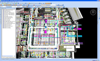
So we've all seen Navisworks and have appended models to create a composite model like so.


Click on all images if blurry for higher-res
All Images by Brad Hardin, barnhart-heery, inc.


But what a lot of folks might not know is that once you have created your composite model you can select either an entire file and translate it or you can select an individual component and translate it. Keep in min that we are working in an .NWF file format. I'll talk later on why .NWD file translation is wonky.

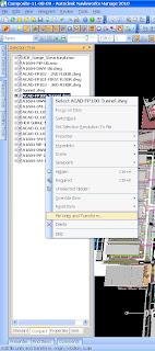
That said to translate an entire file, highlight on the Selection Tree and right click on the "File Units and Transform" command as shown below.
This then pulls up the transform dialog box that allows you to enter in transformed coordinates and essentially move the entire file by entering in fett, inches or metric units depending on your system.

While I don't recommend this tool to set up the alignment of your files, it is awfully handy when trying to relocate the entire elevation of say Fire sprinkler lines or a "what if" sturcture scenario, etc... Handy but usually our job as "BIM folk" is to change bits and pieces of a total design and make shifts here and there to reduce clashes and resolve design issues. Which takes us to transforming components....

Transforming components is not that complicated either. However ,I would recommend a process interjection here. If you haven't used the "measure" tool in Navisworks then I will introduce the newbies to it. If you are a seasoned vet and have this under control then I would recommend skipping ahead to the next paragraph that begins with "This image below..." (kind of like choose your own adventure).


To begin, if you want to move components in Navisworks, typically you need to know some measure of distance to enter as it isn't as easy to move components around as it is in Revit to measure the distance from one system to another to find out "clear space".

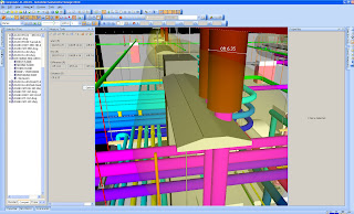
The image below shows a clash in between an electrical conduit sleeved slab penetration and a deck mounted utility light. In this case, I always look at moving the "LCD" - "least common denominator" which in this example is the lighting layout as the conduit sleeve needs to stack for all three floors of this design, instead of jog. So we're moving some lights. But how far Brad? How far are we moving those lights? Well I'm about to tell you.


Open the Measure tool from your dialog box, looks like this:


Then click on one end of the conduit sleeve (with snaps turned on...hit Help if you don't know how to do this) to the other end.


*Note - Keep in mind this is to find a ballpark measurement, if you want to get really exact in Navis, I recommend selecting your zoom tool and then right clicking on your view cube wheel and selecting orthographic instead of perspective and aligning your view to the dimension you need.

As you can see from the image below the sleeve is about 6.11" Which we will round up to 7", since there is no equipment to the left of the light and transform the light 7" to see if this clears our clash.


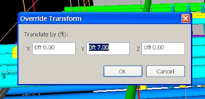
By highlighting the component, in this case the light, and right clicking, I will select the Override Item - > Override Transform. This will bring up a dialog box that looks like the image below. Here I will enter 7" in the Y direction that I wish to transform the object.


Click OK and "Voila!" now you can see that the light has shifted (not the entire file) and that we are visibly clear of the previous clash.


This type of quick review and alteration is a "Must Know" for the BIM Manager and one that comes in pretty handy when doing a live coordination meeting or doing some quick "what-if" scenarios among other things.

Let me know if you have anything to add to the tutorial as input is always welcome and have a great rest of the week!